6.6 DESIGN OF TURBOPUMP BEARINGS, SEALS, AND GEARS
Turbopump Bearing Design
A turbopump shaft is supported by two or more bearings. The loads on the bearings are the result of forces which act on the shaft or on the parts supported by the shaft. These forces may be divided into two classes: those which act at right angles to the shaft axis (radial forces), and those which act parallel to the shaft axis (thrust loads).
Radial loads on turbopump bearings may result from one or more of the following sources: (1) Weights of parts such as shafts, pump impellers, turbine rotors, gears (2) Centrifugal forces due to unbalance of these rotating parts (3) Forces due to inertia, resulting from rapid acceleration (4) Resultant radial forces on the impeller due to nonuniform pressure distribution in the discharge volute of the pump (5) Tangential or torque forces induced by the gears
Thrust loads on turbopump bearings may result from one or more of the following sources: (1) Weight of rotating parts mounted on a vertical shaft (2) Unbalanced axial thrust of the pumps (3) Resultant axial thrust on the turbine rotor blades
For the turbopumps of liquid rocket engines, high-speed ball and roller bearings are used almost exclusively. A typical two-bearing design is shown in figure 6-7. A ball bearing carries both radial and thrust loads. It is paired with a roller bearing which carries only radial loads, however, of a higher magnitude. A typical three-bearing arrangement is shown in figure 6-63. The shaft radial loads are carried by a single roller bearing at the turbine end and by a roller and a ball bearing on the pump side. The ball bearing also absorbs the thrust loads. As a rule, the shaft thrust loads in a turbopump are carried by a single or dual bearing located at one end of the shaft. Thus loads from thermal expansion or contraction of the shaft are avoided.
Bearing design data with regard to loadcarrying capacity, operating speed, and service life are usually furnished by the manufacturers. The useful life of a bearing is dependent upon its speed and load, and may be expressed by the correlation:
where design factor usually furnished by manufacturer. If a bearing is subjected to both thrust and radial loads, the two can be combined into a single equivalent radial load:
where equivalent radial load used for bearing selection, lb =actual radial load, lb actual thrust load, lb design coefficient usually furnished by manufacturer Rocket turbopump bearings quite commonly are cooled and lubricated by the propellants pumped. They are usually operated at very high " " values, a parameter which is the product of the bearing bore (millimeters), and the bearing rotative speed (rpm).
Propellant lubrication has the advantage of eliminating an additional lubricant supply system, and of simplifying bearing sealing problems. The following are important design considerations for propellant-lubricated bearings: (1) Characteristics of the propellants, such as thermal stability, operating temperature, chemical inertness, viscosity. (2) Compatibility of the bearing materials with the propellants. The application of certain high-strength alloys is sometimes limited by the propellants used. The " " rating is convenient when selecting high-speed ball or roller bearings. As the rotative speed of a bearing increases, contact fatigue of the outer race caused by centrifugal loads of the balls or rollers may cause failures. In addition, bearing contact speeds will result in nonrolling phenomena with attendant failures caused by overheating. Through proper selection of the bearing geometry, these problems can be minimized, and the rating increased. Note that for a given horsepower rating, the shaft size based on allowable stress does not decrease proportionally with the increase of shaft design speed. Thus the required bearing value rapidly increases for high-speed turbopumps. As a result, especially for liquid hydrogen application, the turbopump rpm is often determined by the limits of the bearings.
A most important bearing design consideration is the expected operating life of the rocket engine. The bearings must have adequate statistical probability of conforming with this requirement. A generally accepted life rating for ball and roller bearings is the "B-10 life." The term denotes the operating life (hours) of a "population" of bearings at a given load and speed, at the expiration of which statistically 10 percent of them will have failed. Of course, in actual rocket engine operation, component reliability must be much higher. Bearing life at a given load and speed varies inversely with reliability. For instance, the B-1 life ( 99 percent reliability) is one-tenth of the B-10 life ( 90 percent reliability), or one-fiftieth of the B-50 life (50 percent reliability). Therefore, turbopump bearings are generally designed for a B-10 life of at least 100 hours. This corresponds to a B-1 life of 10 hours, or a B- 0.1 life ( 99.9 percent reliability) of 1 hour, the latter by order of magnitude being the life the bearing most likely will actually see. For critical applications, an even higher life rating may be selected.
Figure 6-61 presents the centrifugal load limits in terms of 10,100 , and 1000 hours of B-10 life for a typical ball bearing design (extralight series).
The stress-limiting values of roller bearings are much higher than for ball bearings; however, it is extremely difficult to control the temperature rise in a roller bearing, if the value is above , due to excessive cage slip. Generally, rocket turbopump bearings have been successfully operated at values up to . Limited test information indicates possible satisfactory operation at .
Dynamic Seal Design
The principal dynamic, i.e., rotating seal types used in liquid rocket turbopumps are the labyrinth, face-riding, and shaft-riding seals. Satisfactory seal operation depends upon good design which considers many factors, including
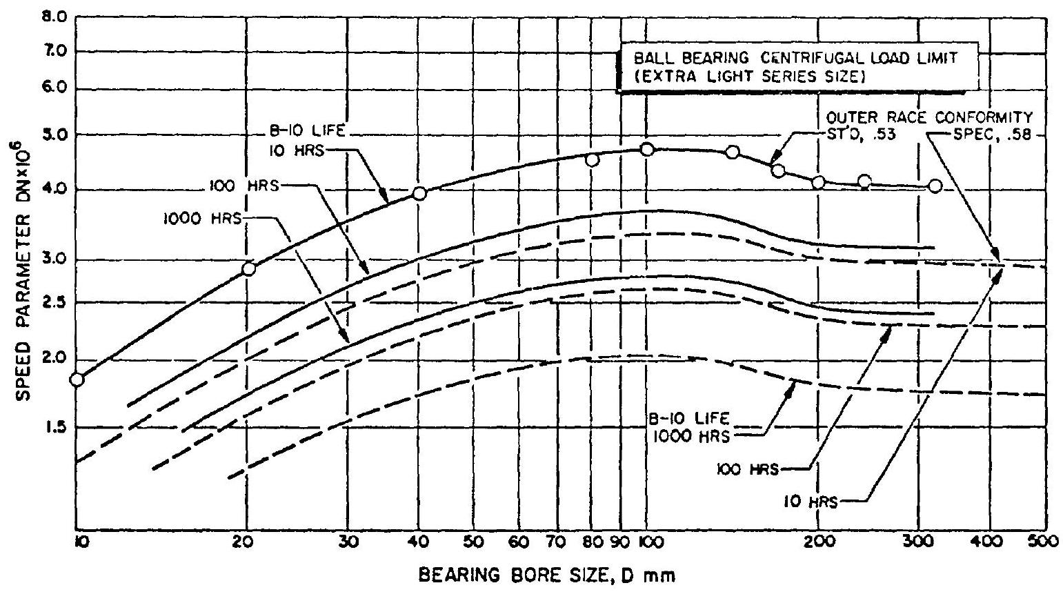 Figure 6-61.-Ball bearing centrifugal load DN limits.
fluid pressure surges, vibration, expansion and contraction of sealing components, contact pressure between sealing surfaces, rubbing velocities of the sealing surfaces, smooth and frictionfree operation of internal sealing parts, and on squareness of the sealing surfaces. Any influence which directly or indirectly subsequently alters these factors can cause improper operation of the seal.
As shown in figure 6-62, the labyrinth seal is a clearance-type seal. The fluid tending to pass through the sealing interface is throttled many times and is forced to follow a devious path. The function of a labyrinth seal is not to prevent fluid leakage entirely, but rather to reduce leakage to a reasonable level at a minimum of friction and wear. The amount of leakage through a labyrinth seal can be estimated by the correlation
where leakage rate, seal clearance area, in pressure differential across the seal, density of the fluid seal leakage coefficient, established experimentally Labyrinth seals are used for the wearing rings of pump impellers, as well as for the rotating seals attached to the sealing diaphragm between two turbine stages.
In a face-riding-type seal the sealing is accomplished through rubbing contact between the precision-lapped faces of a floating seal washer and a shoulder ring. The mating faces are at a right angle to the axis of rotation. As shown in figure 6-62, the floating seal washer is attached to a metal bellows. The bellows, in turn, is welded to a stationary seal housing which is secured and statically sealed to the casing. The bellows provides flexibility and spring force to the contact face, permitting it to follow axial and angular movement without leakage. Sometimes a lip seal is used in conjunction with a spring-loaded floating washer, instead of a bellows.
The shaft-riding seal (fig. 6-62) consists of a seal housing, a seal retaining plate, and several seal segments. The segments form a ring around the shaft and are held against it by garter springs.
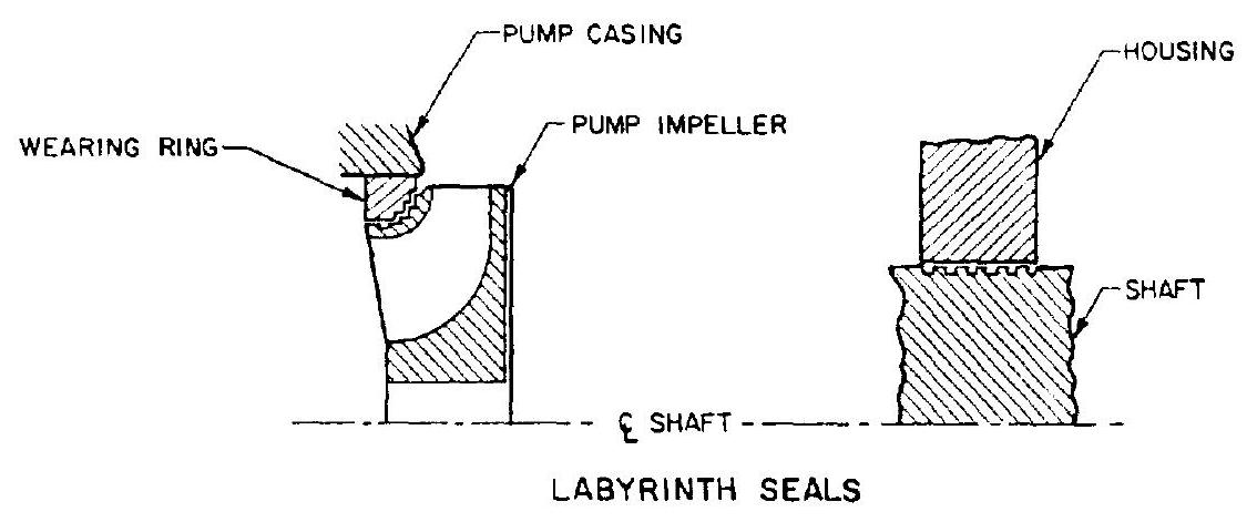
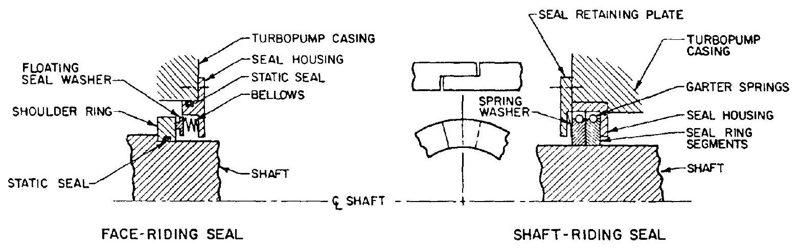 Figure 6-62.-Principal turbopump dynamic seal types.
Thus self-adjusted dynamic sealing is accomplished between shaft outside diameter and segment inside diameter. Axially, the segments are forced against a flat surface of the seal housing by a retaining plate and a spring washer, thus providing a static seal. Shaft-riding seals tend to occupy less space than the face-riding seals.
A wide variety of materials is available for floating seal washers and seal ring segments. Carbon is used most frequently. The rubbing seal faces on shoulder ring or shaft must be hardened or plated, and lapped to a very smooth finish. The seal face rubbing speed should not exceed 300 fps . Frequently, vent or purge lines are connected to the cavities between two or more dynamic seals installed in series. This assures positive sealing for critical applications such as interpropellant seals.
Turbopump Gear Design
The gear trains used in liquid rocket turbopumps (fig. 6-16) afford speed differentials between turbine, pumps and accessory drives, and also sometimes between a pump impeller and a low-speed inducer. Gear arrangement and geometry depend upon power transmitted, propellants, speed ratio, and other factors. During operation, the gears are cooled and lubricated with oil, or with the propellant being pumped.
The gears are usually housed in an aluminum casing. To minimize weight further, webs are held as thin as possible as are cross sections at the rim and hub. The hubs are often internally splined for best results. Spur gears are most widely used, since they minimize thrust on bearings. Tooth loads and speeds in turbopump gears are very high. The designer, therefore, must achieve high tooth strength and high resistance to wear. Turbopump gears are usually made of high-alloy steel, with the tooth surfaces hardened by either case carburizing or induction hardening. If possible, the tooth surface should be accurately finished by a grinding process. Materials and dimensional tolerances of turbopump gears must be held under very close control during manufacturing.
To improve gear life and load-carrying stability, certain modifications to standard design practices can be applied. Pinions are frequently made with long addendum and gears with short addendum to adjust tip-sliding velocities and to strengthen the pinion. Furthermore, pinion tooth thicknesses are often increased, at the expense of gear tooth thickness. High pressure angles as high as , or may be applied to reduce contact stresses on the tooth surface and to increase the width of the tooth at the base. Involute-profile modifications are often also made to compensate for bending and to keep the tips from cutting the mating part.